Processing math: 100%
<< Chapter < Page Chapter >> Page >

A circuit problem

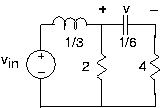
You are given the depicted circuit .

  1. Find the differential equation relating the output voltage to the source.
  2. What is the impedance “seen” by the capacitor?

Analog computers

Because the differential equations arising in circuits resemble those that describemechanical motion, we can use circuit models to describe mechanical systems. An ELEC 241 student wants tounderstand the suspension system on his car. Without a suspension, the car's body moves in concert with the bumpsin the raod. A well-designed suspension system will smooth out bumpy roads, reducing the car's vertical motion. Ifthe bumps are very gradual (think of a hill as a large but very gradual bump), the car's vertical motion shouldfollow that of the road. The student wants to find a simple circuit that will model the car's motion. He istrying to decide between two circuit models ( [link] ).

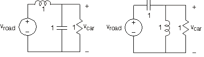
Here, road and car displacements are represented by the voltages vroad(t) and vcar(t) , respectively.

  1. Which circuit would you pick? Why?
  2. For the circuit you picked, what will be the amplitude of the car's motion if the road has adisplacement given by vroad(t)=1+sin(2t) ?

Transfer functions and circuits

You are given the depicted network .

  1. Find the transfer function between Vin and Vout .
  2. Sketch the magnitude and phase of your transferfunction. Label important frequency, amplitude and phase values.
  3. Find vout(t) when vin(t)=sin(t2+π4) .

Fun in the lab

You are given an unopenable box that has two terminals sticking out. You assume the box contains a circuit. Youmeasure the voltage sin(t+π4) across the terminals when nothing is connected to them and the current 2cos(t) when you place a wire across the terminals.

  1. Find a circuit that has these characteristics.
  2. You attach a 1 H inductor across the terminals. What voltage do you measure?

Dependent sources

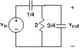
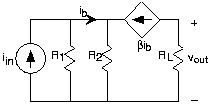
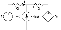
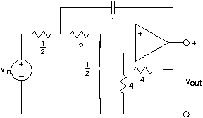
Find the voltage vout in each of the depicted circuits .

Circuit a

Circuit b

Operational amplifiers

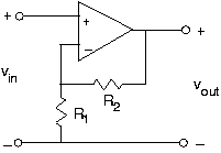
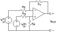
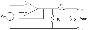
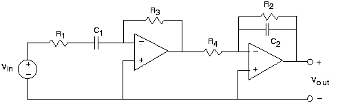
Find the transfer function between the source voltage(s) andthe indicated output voltage for the circuits shown in [link] .

Op-amp a

Op-amp b

Op-amp c

Op-amp d

Op-amp circuit

The following circuit is claimed to serve a useful purpose.

  1. What is the transfer function relating the complex amplitude of the output signal, the current Iout , to the complex amplitude of the input, the voltage Vin ?
  2. What equivalent circuit does the load resistor RL see?
  3. Find the output current when vin=V0e-tτ .

Why op-amps are useful

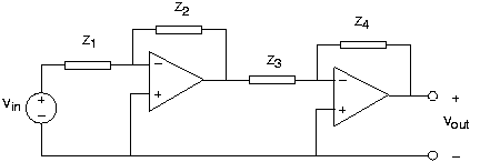
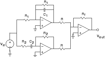
The circuit of a cascade of op-amp circuits illustrate the reason whyop-amp realizations of transfer functions are so useful.

  1. Find the transfer function relating the complexamplitude of the voltage vout(t) to the source. Show that this transfer function equals the product of each stage's transfer function.
  2. What is the load impedance appearing across the first op-amp's output?
  3. [link] illustrates that sometimes “designs” can go wrong. Find the transferfunction for this op-amp circuit , and then show that it can't work! Why can't it?

Operational amplifiers

Consider the depicted circuit .

  1. Find the transfer function relating the voltage vout(t) to the source.
  2. In particular, R1=530Ω , C1=1μF , R2=5.3 , C2=0.01μF , and R3=R4=5.3 . Characterize the resulting transfer function anddetermine what use this circuit might have.

Designing a bandpass filter

We want to design a bandpass filter that has transferthe function H(f)=10i×2πf(iffl+1)(iffh+1) Here, fl is the cutoff frequency of the low-frequency edge of the passband and fh is the cutoff frequency of the high-frequency edge. We want fl=1kHz and fh=10kHz .

  1. Plot the magnitude and phase of this frequency response. Label important amplitude and phase valuesand the frequencies at which they occur.
  2. Design a bandpass filter that meets thesespecifications. Specify component values.

Pre-emphasis or de-emphasis?

In audio applications, prior to analog-to-digital conversion signals are passed throughwhat is known as a pre-emphasis circuit that leaves the low frequencies alone but provides increasinggain at increasingly higher frequencies beyond some frequency f0 . De-emphasis circuits do the opposite and are applied after digital-to-analog conversion. Afterpre-emphasis, digitization, conversion back to analog and de-emphasis, the signal's spectrumshould be what it was.

The op-amp circuit here has been designed for pre-emphasis or de-emphasis (Samantha can'trecall which).

  1. Is this a pre-emphasis or de-emphasis circuit? Find the frequency f0 that defines the transition from low to highfrequencies.
  2. What is the circuit's output when the input voltage is sin(2πft) , with f=4kHz ?
  3. What circuit could perform the opposite function to your answer for the first part?

Active filter

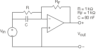
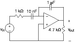
Find the transfer function of the depicted active filter .

This is a filter?

You are given a circuit .

  1. What is this circuit's transfer function? Plot the magnitude and phase.
  2. If the input signal is the sinusoid sin(2πf0t) , what will the output be when f0 is larger than the filter's “cutoff frequency”?

Optical receivers

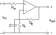
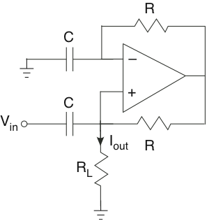
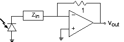
In your optical telephone, the receiver circuit had the form shown .

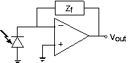
This circuit served as a transducer, converting light energy into a voltage vout . The photodiode acts as a current source, producing a current proportional to the light intesityfalling upon it. As is often the case in this crucial stage, the signals are small and noise can be aproblem. Thus, the op-amp stage serves to boost the signal and to filter out-of-band noise.

  1. Find the transfer function relating light intensity to vout .
  2. What should the circuit realizing the feedbackimpedance Zf be so that the transducer acts as a 5 kHz lowpass filter?
  3. A clever engineer suggests an alternative circuit to accomplish the same task. Determine whether the idea works or not. If itdoes, find the impedance Zin that accomplishes the lowpass filtering task. If not, show why it does not work.

Reverse engineering

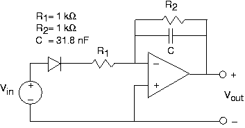
The depicted circuit has been developed by the TBBG Electronics design group. They are trying to keep itsuse secret; we, representing RU Electronics, have discovered the schematic and want to figure out theintended application. Assume the diode is ideal.

  1. Assuming the diode is a short-circuit (it has been removed from the circuit), what is the circuit'stransfer function?
  2. With the diode in place, what is the circuit's outputwhen the input voltage is sin(2πf0t) ?
  3. What function might this circuit have?

Get Jobilize Job Search Mobile App in your pocket Now!

Get it on Google Play Download on the App Store Now


Source:  OpenStax, Fundamentals of electrical engineering i. OpenStax CNX. Aug 06, 2008 Download for free at http://legacy.cnx.org/content/col10040/1.9
Google Play and the Google Play logo are trademarks of Google Inc.

Notification Switch

Would you like to follow the 'Fundamentals of electrical engineering i' conversation and receive update notifications?

Ask